How to Fix Common Inverter Problems and Error Codes?

Time:2026-09-14 Author:Oliver
0%

An inverter can stop working without warning, leaving a dark display, a silent motor, or a flashing error code. Learning How to fix common inverter problems and errors begins with careful observation, not immediate part replacement. A code such as E01, F05, or Overload may mean different things across brands and models. Always check the manufacturer’s manual before testing or resetting the unit.

Safety matters. Disconnect the power source, wait for capacitors to discharge, and use suitable protective equipment. Inspect the cables for loose terminals, burned insulation, moisture, or corrosion. A small screwdriver mark near a terminal can reveal repeated vibration. Measure input voltage with a properly rated multimeter, but avoid live testing unless you understand electrical hazards. Some faults require a qualified electrician.

This guide explains practical checks for overheating, overload trips, low-voltage alarms, communication failures, and unexplained shutdowns. It also shows when a reset may help and when it could hide a serious defect. Do not assume every alarm indicates a failed inverter. Weak batteries, restricted airflow, incorrect settings, and poor connections often cause similar symptoms. Even experienced technicians can misread a code after a rushed inspection. That possibility deserves attention. Reliable troubleshooting means recording the exact code, operating conditions, recent changes, and reset history. If the inverter smells burned, shows damaged components, or repeatedly trips protection, stop using it and seek professional service.
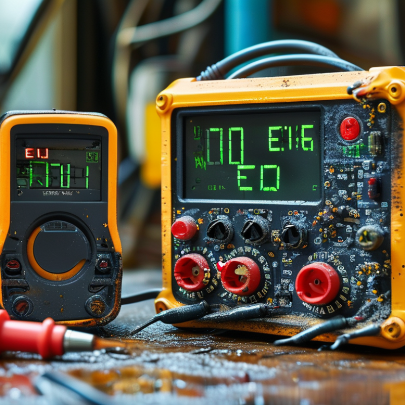
How to Fix Common Inverter Problems and Error Codes?

Identify Inverter Type, Ratings, and IEC 62109 Safety Limits

When an inverter shows an error code, identify its type before touching the wiring. A grid-tied unit behaves differently from an off-grid or hybrid model. Read the nameplate carefully. Record the DC input range, maximum current, AC voltage, output frequency, and rated power. These figures define the safe operating window.

Check the code against the installation manual, not a random online chart. A “high DC voltage” warning may come from cold-weather panel voltage, incorrect string design, or a faulty measurement circuit. A “grid fault” can indicate abnormal voltage, frequency, grounding, or a disconnected utility supply. Measure only with suitable instruments and protective equipment. Isolate both DC and AC sources, then wait for the stated discharge time. Small capacitors can still hold dangerous energy.

IEC 62109 sets important safety requirements for power converters used in photovoltaic systems. It addresses insulation, protective bonding, creepage distances, temperature, enclosure safety, and abnormal operating conditions. It does not provide permission to bypass a shutdown limit. Never increase a protection threshold without documented approval from the equipment manufacturer and a qualified technician. Ratings also change with ambient temperature, ventilation, altitude, and installation position. A neglected detail can explain an intermittent fault. Still, diagnosis is not always clean; a code can be a symptom rather than the failed component. Photograph the display, record weather conditions, and compare readings over time. That evidence often prevents a rushed replacement.

Read the Error Code and Compare DC/AC Values With Nameplate Data

When an inverter shows an error code, record it before switching the system off. The code may indicate low DC voltage, overcurrent, overheating, or an AC-side fault. I have found that a clear photo of the display prevents memory errors later. Check the installation manual, then inspect cables, terminals, fuses, ventilation, and visible damage. Do not open energized equipment. Use suitable test instruments, protective equipment, and a qualified technician where required.

Measure the DC voltage at the inverter input and compare it with the nameplate range. A reading below the minimum can point to weak batteries, long cables, loose terminals, or shading in a solar array. Measure polarity too. It is an easy detail to miss.

On the AC side, check voltage, frequency, and current against the nameplate values. Compare measurements under similar load conditions, because startup surges can briefly exceed normal current. If the nameplate allows 230 V and the meter shows 198 V under load, investigate the supply and wiring rather than repeatedly resetting the inverter.

If the output is unstable, stop testing and document the readings. Small mistakes happen. I once trusted a no-load voltage and overlooked a severe drop when equipment started. Record the time, load, temperature, error code, and meter location. These details help a technician separate an inverter fault from a battery, grid, or wiring problem.

Test PV Strings, Batteries, Fuses, and Grounding Step by Step

How to Fix Common Inverter Problems and Error Codes?

Begin with the error code and the inverter’s event log. Record the time, operating mode, and battery voltage. Turn off AC and DC sources before opening covers. Wear rated gloves and use insulated test leads. A PV string may show normal voltage but still fail under load. Measure each string’s open-circuit voltage, polarity, and current. Compare readings with the system design. A sharp difference often indicates a loose connector, damaged cable, or shaded panel.

Tips: Label every string before testing. Photograph cable positions. Do not trust color alone. Check twice.

Inspect the battery next. Measure its resting voltage, then observe voltage during startup or charging. A sudden drop suggests weak cells, poor terminals, or an undersized cable. Check torque marks and corrosion. For fuses, isolate all power and verify continuity with a meter. A fuse can look intact while failing electrically. Replace it only with the specified type and rating. Never bridge a blown fuse.

Test grounding from the inverter chassis to the grounding point. The connection should be mechanically firm and electrically continuous. Inspect for paint, rust, or loose lugs beneath the terminal. An unstable ground can trigger insulation or leakage alarms. I once blamed the inverter too quickly; the real fault was a crushed cable near the battery rack. That mistake reinforced a practical lesson: test the simplest physical points before replacing expensive equipment. Stop when measurements conflict, and request qualified service for high-voltage faults.

Check Grid Voltage, Frequency, and IEEE 1547 Ride-Through Settings

When an inverter reports grid overvoltage, undervoltage, or frequency errors, measure the grid before changing settings. Use a calibrated meter at the inverter terminals, not only at the main panel. Record voltage on every phase, both with and without load. Check frequency during morning starts and heavy afternoon demand. Small variations can reveal loose connections, long cable runs, or an overloaded transformer.

Compare the readings with the utility interconnection requirements and the inverter’s approved operating range. IEEE 1547 ride-through settings determine how long the inverter remains connected during voltage or frequency disturbances. They are not simple alarm limits. A setting may require the inverter to stay online through a short event, then disconnect after a defined delay. Requirements can vary by grid authority, system category, and commissioning date. Never widen limits casually.

Review event logs before resetting the unit. Match each trip with the measured voltage, frequency, time, and weather conditions. A brief reset may appear successful. It can also hide a recurring fault. Inspect terminals for heat damage and verify phase balance under load. If readings are normal but trips continue, check configuration files, control firmware, and communication wiring through qualified personnel. I have found that rushed testing often misses a voltage drop that appears only when pumps or compressors start. That detail matters. Follow local electrical rules, lockout procedures, and utility approval requirements before modifying ride-through parameters.

Reset, Verify Rapid Shutdown Within 30 Seconds, and Confirm Safe Operation

When an inverter displays an error code, record the code, time, weather, and operating conditions before resetting it. A reset may clear a temporary communication or grid event, but it does not repair damaged wiring, overheating, or insulation faults. Follow the equipment manual and local electrical requirements. Do not remove covers or probe live terminals unless you are a qualified professional with properly rated test equipment.

For a controlled reset, disconnect the system in the sequence specified by the manufacturer, usually separating the AC and DC sources. Keep clear of exposed conductors, then wait for the stated discharge period. Restore power only in the correct order. Watch the display for normal startup behavior. The fault should not return immediately. If it does, stop repeating the reset. That habit can hide the symptom and delay a proper diagnosis.

Rapid shutdown needs direct verification, not assumption. Activate the shutdown device, then use an appropriately rated meter to check the array conductors after 30 seconds. Voltage should fall within the safe limit specified for that system. Check from a safe position, and never rely only on the screen or indicator light. If voltage remains higher than expected, treat the circuit as energized and call a qualified technician. Afterward, confirm the inverter starts normally, output readings are stable, and no warning appears. Recheck the enclosure for unusual heat, noise, moisture, or burning smells. Small clues matter. One imperfect check can undermine an otherwise careful repair.

FAQS

Where should grid voltage be measured when an inverter reports a voltage error?

Measure at the inverter terminals with a calibrated meter. Check every phase, with and without load. A panel reading may miss cable voltage drops.

When should grid frequency be checked?

Check frequency during morning startup and heavy afternoon demand. Small changes can expose an overloaded transformer or loose connection.

What should be reviewed before changing ride-through settings?

Compare measured values with local utility requirements and the inverter’s approved operating range. Never widen limits casually. Settings may control connection time during disturbances.

Why should event logs be checked before resetting the inverter?

Match each trip with voltage, frequency, time, weather, and operating conditions. A quick reset can fool you. It may hide a recurring fault.

What physical checks can reveal an electrical problem?

Inspect terminals for heat damage and check phase balance under load. Pumps or compressors may cause brief voltage drops. That detail matters.

How should an inverter be reset safely?

Record the error code and conditions first. Follow the specified AC and DC shutdown sequence. Wait for the required discharge period. Restore power in the correct order.

What should happen if the same fault returns immediately after resetting?

Stop repeating the reset. Persistent faults may involve wiring, overheating, insulation, configuration, or communication problems. Arrange qualified testing.

How can rapid shutdown be verified?

Activate the shutdown device and measure array conductors after 30 seconds. Voltage must reach the system’s stated safe limit. Never trust only a display light.

What should be checked after normal startup?

Confirm stable output and no warnings. Inspect for unusual heat, noise, moisture, or burning smells. One imperfect check can undermine a careful repair.

Conclusion

How to fix common inverter problems and errors begins with identifying the inverter type, rated voltage, current, power limits, and applicable IEC 62109 safety requirements. Start by reading the displayed error code and comparing the inverter’s DC input and AC output values with the nameplate specifications. Then inspect the system step by step, including PV strings, battery connections, fuses, cable condition, terminals, and grounding. Always isolate power safely and use properly rated test equipment.

For grid-connected systems, verify the grid voltage and frequency, then review the configured ride-through settings in accordance with applicable IEEE 1547 requirements and local regulations. After correcting the cause, perform a controlled reset and observe the inverter during startup. Confirm that rapid shutdown operates within 30 seconds when required, and check that no new warnings, abnormal sounds, overheating, or unstable readings appear. If the fault remains or safe testing is not possible, stop work and contact a qualified technician.

Oliver

Oliver

Oliver is a seasoned marketing professional with a wealth of expertise in driving brand awareness and engagement. With a deep understanding of our company's product offerings, he consistently delivers high-quality content that enriches our professional blog. His insights not only shed light on......